1:
Is the 620A is in the
“RMT_STP” mode?
On the bottom line of the display it must read “LCL” for front
panel button control.
Go to the Programmer Configuration selection and change the mode
from “EXT COMPUTER” (RMT) to “FRONT PANEL,” (LCL) or make the
change from the computer if the selection is available.
2:
Is the “PROGRAMMER
SYNC” enabled?
From the “CONFIG
PROGRAMMER” selection, page down six times.
If the display indicated the Sync is
Enabled.
Push the SEL button to select
Disabled.
Push Reset and try Run again.
3:
Is there a flashing “S1 or S2” in the
ALM: field on the front panel?
If the S1 or S2 is flashing the offending channel will also be
displaying either P.OP or RANGE in the PV field on the front
panel display.
P.OP
- indicates a probe open condition.
Either the thermocouple or RTD input
is open or the current or voltage input is out of the usable
range.
Correct the open probe condition and the control channel will
immediately read the current PV value.
If the P.OP condition can not be corrected the Analog input
board of the instrument may be damaged.
Contact TMC Services for repair services.
RANGE
- indicates that programmed or manual setpoint entered is
outside of the Span-Setpoint Limits range configured for the
control channel.
If the setpoint appears to be within the desired usable range
check the controllers Span-Setpoint limits.
They may have been changed and not
restored.
The limits determine the Max and Min
setpoints that can be entered.
They also determine the total span
of the controller.
A Max of 200 and Min of -100
establish a span of 300.
Manual Mode:
From the Manual Mode screen enter a new setpoint within
acceptable limits.
The controller will immediately
resume operation.
Programmer Mode:
1 - Check the programmed setpoint.
It must be within the usable span of
the controller
2 – When starting a program, or changing and starting on a new
step, a corrupt setpoint can be
generated.
When this occurs the setpoint must
be corrected to “wake up” the controller.
Select
the manual mode and enter a setpoint as mentioned above.
Be sure to place the control channel back into programmer mode
and try running the program.
3 - If the span was incorrectly set and is adjusted to correct
values the control channel will correct itself
and resume operations.
4:
Is there a flashing “L1
or L2” in the ALM: field on the front panel?
The L1 (CH1) and L2 (CH2) are DEV (deviation) alarm indicators.
The DEV value can be entered by the operator in the
Manual Mode or in the Edit mode on each step of the program.
There is a “Common DEV Alarm” output on TB1 of the A2225 Output
Interface PCB. This
output goes Active whenever the L1 or L2 ALM: display is
flashing.
Each channels DEV alarm can be configured for 4 different modes in the
Programmer Configuration.
In any mode, the L1 or L2 will display on the front panel and the output
pin will be active if the DEV condition exists.
The available modes for each channel are:
1 – During DEV the programmer Runs or Stops.
2 – Alarm Output Resets Automatically or Manually.
Run – Automatic Reset:
If a DEV condition exists.
The programmer will continue to run the program.
The L1 or L2 will flash in the ALM field and the output
will be active.
When the DEV error is corrected the output de-activates and the L1 or L2
display goes blank.
Run – Manual Reset: If a
DEV condition exists.
The programmer will continue to run the program.
The L1 or L2 will flash in the ALM field and the output
will be active.
When the DEV error is corrected the 620A will continue to run with the
output active and L1 or L2 flashing in the ALM field.
If the DEV condition no longer exists the Run button
must be pushed to
acknowledge the DEV alarm was active.
The output will de-activate and the L1 or L2 display goes
blank.
Stop – Automatic Reset:
If a DEV condition exists.
The programmer will stop (freeze/hold).
The clock stops and the setpoints are latched at the
current values. The
L1 or L2 will flash in the ALM field and the output will be
active.
When the DEV error is corrected the output de-activates, the L1 or L2
display goes blank, and the programmer automatically resumes
operation from the point it was stopped.
Stop – Manual Reset: If
a DEV condition exists.
The programmer will stop (freeze/hold).
The clock stops and the setpoints are latched at the
current values. The
L1 or L2 will flash in the ALM field and the output will be
active.
If the DEV condition no longer exists the Run button
must be pushed to
acknowledge the DEV alarm was active.
When the DEV error is corrected, and the run button is
pushed the output de-activates, the L1 or L2 display goes blank,
and the programmer resumes operation from the point it was
stopped.
Note: The error must be within the DEV limits for the program to resume
when the run button is pushed.
Otherwise the program will remain stopped.
Back to the top.
My Program runs but the setpoint does not
change.
Look at the setpoint field on the front
panel.
If the decimal point is the letter
“m” then that channel is in
the manual setpoint mode.
Manual setpoints override programmed
setpoints in a program.
Select “Manual” from the main menu and
change the channel from Manual to Programmer.
The “m” will go away and the decimal
point will return indicating the controller channel is now in
programmer mode.
Back to the top.
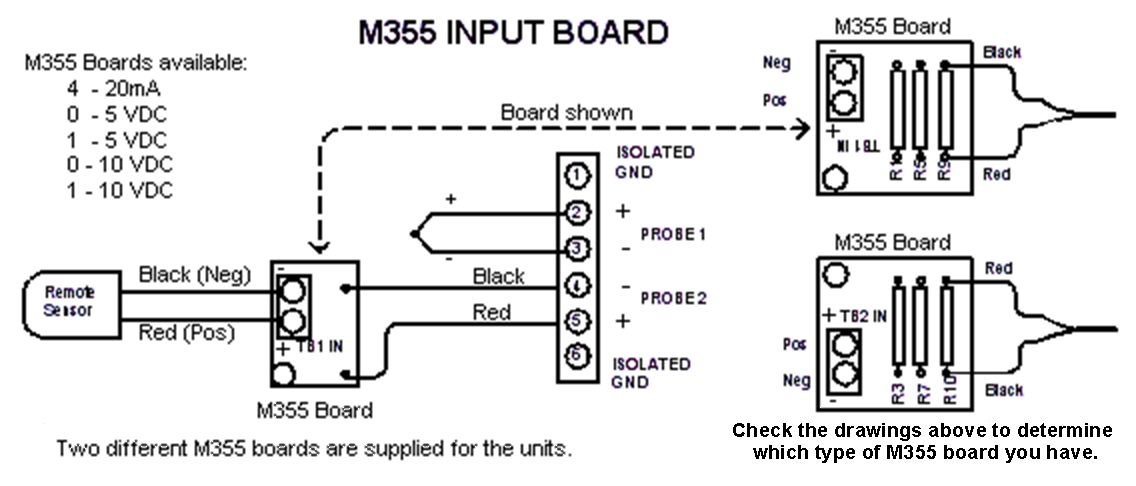
My control
channel reads P.OP or a very low or high value.
How do I check it?
A simple check can be made to verify that the analog board input is
functional. This check can not be used for RTD inputs.
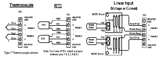
Thermocouple or Linear input types:
Go to the Controller configuration and select Degrees C for the Units
and Type_T_TC for the Input.
Remove the sensor wires from the input terminal block.
Using a jumper (a piece of wire or paper clip works nicely) short the
thermocouple input pins probe 1 (or 2) plus and minus.
The control channel should read the temperature of the Cold Junction
Device, approximately 25 to 40 deg C and be stable. If not,
contact TMC Services for repair options.
If it is good a calibration may be necessary.
Configure the channel for its correct units and input
type and perform a calibration.
RTD:
Disconnect the three wires from the RTD to the input terminal strip.
Connect a 100 ohm resistor across the Probe 1 plus and minus input pins.
Connect a jumper across the ISO GND and negative input pins.
The controller should read 0.0.
If the reading is off a calibration may be necessary.
If the controller still reads P.OP contact TMC services for repair
options.
Back to the top.
I can't
get anything to work or make changes from the keypad of the
controller.
Is the unit in
“RMT_STP” mode?
Push the “RESET” button on the controller.
If the Bottom line says “RMT” it’s in the remote mode and
will only take commands from a computer.
If the display reads “RMT_STP.”
Push RESET, PAGE DOWN,
4, 1.
Use the arrow keys to position the cursor over the
“EXT_COMPUTER” display.
Push the “SEL” key until the display reads “FRONT
PANEL...”
Push the “RESET” button.
The bottom line should read “LCL_STP.”
You now have front panel control.
Is the unit in “RMT_RUN”
mode?
If so, follow the
procedure below.
If the unit is interfaced with a computer
issue a command to return it to the “LCL” Local front panel
mode.
If the unit is not connected to a computer or
if the communications have been disrupted and can not be
reestablished proceed as follows.
Refer to the diagram below for the A2216, TB6 and
pin outs.
This drawing is
also in the 600(A) / 620 (A) Manual Chapter 7 page 2A (Available
Here).
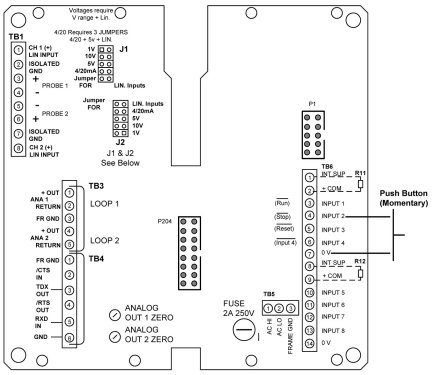
Connect a momentary switch across TB6 pins
4 (Input2, Stop) and 7 (O v).
You may want to leave the switch connected for future
use.
Pushing the switch will put the unit into
the “RMT_STP” mode.
Use the procedure above to regain access to
the LCL (Front Panel) mode of operation.
Back to the top.
I can't
get the RS-232 communications to work with the ToolBOX software.
The ToolBOX software is designed to also
access addressable units with the RS 422 interface.
The ToolBOX software, even in the RS232 mode,
is address sensitive.
The default address is 1.
The 620A address selection is made on the
first page of the “Programmer Configuration” selection.
Using the “SEL” button change to 422.
Either change the 422 address to 1 or note the address
and use it for the address selection on the ToolBox Software.
Don’t forget to change the selection back to
232 before exiting.
Make sure the Baud Rate and Parity match on
both the ToolBox software and the 620A instrument.
Set the
computer Comm port in use to flow control of “xon/xoff.”
The 620A ships with the RS232 connector wired
for “null modem” operation. See below and also in the
600(A) / 620 (A) Manual Chapter 7 page 2A (Available
Here).
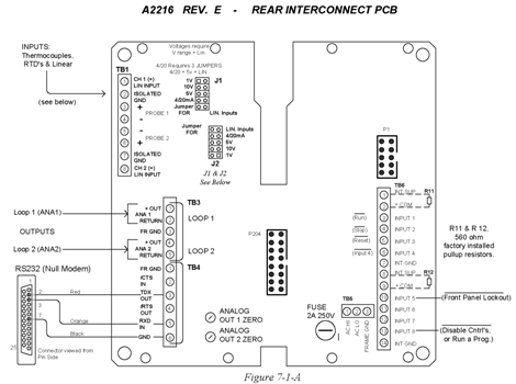
If the RS 232 cable is not null modem swap the
orange and red wires on TB4.
Back to the top.
What is
the difference between an EOP and a LOOP step?
The two steps are similar.
A LOOP step can
repeat a user defined section of the program. When the loop
counter reaches zero the programmer advances to the next step in
the program. Each
loop can perform from 1 to 9999 loops.
Loops can be nested, or two loop steps can be programmed
back to back with 9999 loops to repeat the same section of code
9999 x 9999 or 99,980,001 loops.
Every program
“MUST” be terminated
with an EOP step.
An EOP step can repeat a user defined section of the program, including
loops or nested loops, and will stop when the Cycle counter
reaches zero.
Similar to a Loop step the user
defines the step number of the program to cycle back to and the
number of program cycles to execute, up to 9999.
When the EOP cycle counter reaches zero the
program stops and latches the last CH1 & CH2 setpoint values and
event ON/OFF status.
CAUTION:
Care must be taken when changing the step
number for the EOP or entering a new program with less steps
than the existing program in memory.
Reference the information below for details.
AVOID TURNING AN EOP STEP INTO A LOOP STEP
If a program is entered into a
program location that has an existing program, and the new
program is shorter than the original one, the first EOP step
will be treated as a LOOP step.
When entering a new program into
a location that currently has a program in it, the following
procedure must be taken.
ERASE THE EXISTING PROGRAM - This
is the recommended procedure.
From
the Edit screen move the cursor so it is flashing on the program
(notstep) number, then push the DELSTEP button.
This will erase the existing program and the display will
read "PROGRAM EMPTY, PUSH PAGE DOWN".
Pushing the PAGE DOWN button will insert the first step in the
program location.
Enter the new program terminating it with an EOP step.
ENTER NEW PROGRAM INFORMATION- This can only be done if the new
program has more steps than the existing program.
If it does not then the EOP step from the original
program will still be present somewhere after the new EOP.
The first EOP step will be treated as a LOOP by the
programmer when the program is run.
The second EOP step will be treated as the true EOP.
In this situation the program will cycle (loop) as many
times as indicated by the first EOP, however it will be treated
as a LOOP Step and continue running the programmed information
following the first EOP to include cycling the entire program if
the second EOP step is programmed for more than 1 cycle.
CHECKING THE PROGRAM FOR
ADDITIONAL STEPS FOLLOWING THE EOP.
In the EDIT Mode pushing the page
down button will advance through the program in sequential step
order. However if
the first EOP step is reached and the PAGE DOWN is pressed the
unit will return to step 1 of the program.
The first EOP is recognized as the end of the program.
This WILL NOT indicate if any additional steps are
following the EOP.
Determine the step for the first
EOP in the program (i.e. step 10).
From the EDIT screen position move the cursor to the step
number and push the clear button.
The unit will go to step 1.
With the cursor on the step number, enter the number of
the step following the first EOP step (step11).
If this EOP step is the last step
in the program, the display will flash between the messages
"Invalid Entry" and the Ramp\Soak Program screen.
Push the RESET Button twice to
return the unit to the STOP screen.
This EOP is the last step.
If the programmer indicates
additional programmed steps following this EOP, this information
must be deleted.
Push the DEL STEP button for each additional programmed step.
Be careful not to delete the EOP
step itself. Each
time the DEL STEP button is pushed it deletes the current step
and pulls the following ones forward.
When the correct EOP step is displayed all information
that followed it is now deleted.
Check the program for additional
steps after the EOP (Just to make sure).
Back to the top.
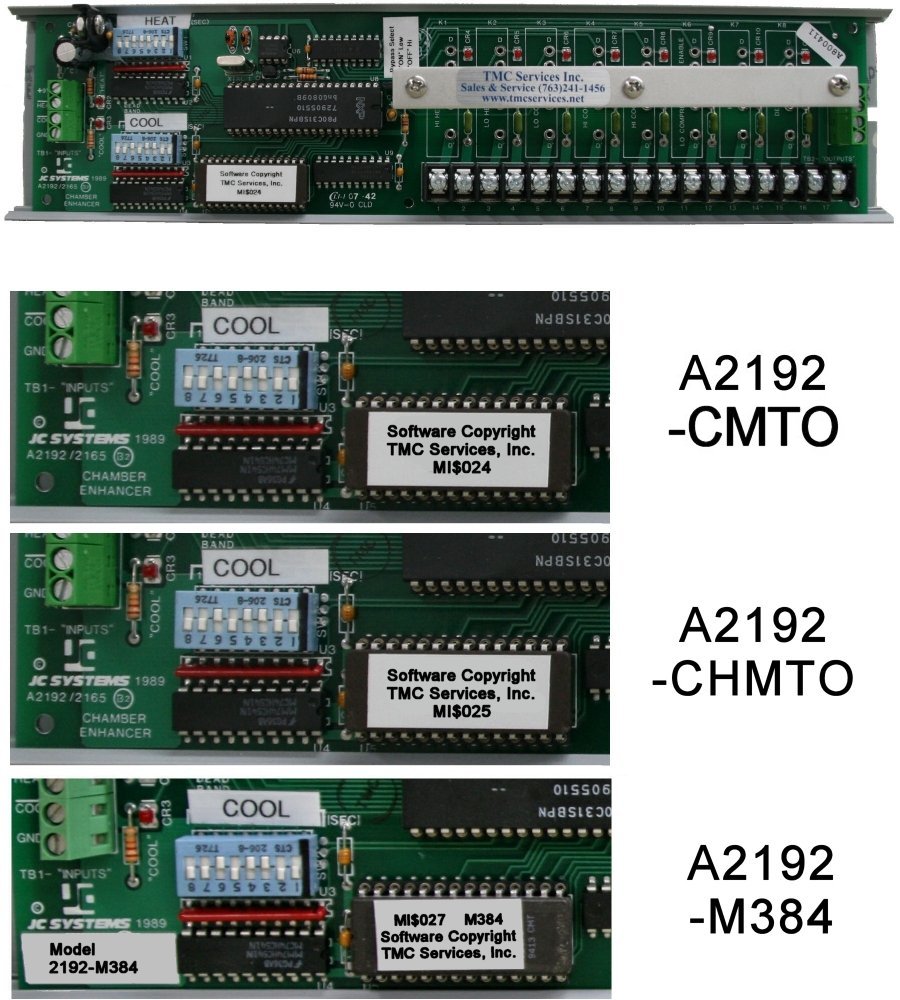
I’m
using an A2192 Chamber Enhancer Board. Are there any
mandatory settings?
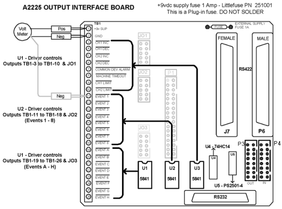
It is imperative that the Inc & Dec Cycle time
of the 620A control channel and the A2192 board Cycle time dip
switch settings match.
If they do not then the information interpreted by the
A2192 will be incorrect and result in incorrect output
functions.
See the A2192 manual for Heat & Cool Dip
switch definitions and settings.
Note:
The Model 620A is connected to the A2192 board by 4
wires. The wires
from the 620A are not pin for pin compatible with the input pins
of the A192.
620A ,TB1 Pin
to A2191, TB1
Pin
1
1
+9vdc
2
4
Gnd
3
2
Inc
4
3
Dec
Back to the top.
I have an Error message.
What does it mean
and what action should I take?
P.OP
on CH1 or CH2 PV:
A P.OP (open probe) condition is displayed
on the control channel PV display.
This message indicates an open input sensor or problem
with the input section of the analog PCB.
Click here
for control channel "P.OP" error
troubleshooting.
“Hardware Failure” or “Error” message:
The Model 620A/600A has several Error
Messages that display to indicate internal problems in the
instrument. The
messages may be displayed as
“Hardware Failures”
or
“Errors”.
These messages do not necessarily indicate
the item or area responsible for the error, but the area
impacted by the problem.
In most cases they provide advanced warning that a
problem has developed needing immediate corrective action or
will need corrective action in the near future.
Some of the messages indicate that a problem exists that
can be corrected and may not repeat itself.
Available Actions to resolve a problem:
In most cases two user actions are
available.
ENT
ignore:
If the
Enter button is
pushed the unit returns to its previous operating state.
Try pushing the Enter button.
After the instrument resets, turn the power
off for a minute or two then turn the power back on.
If the problem was related to scrambled or
incorrect information from an external source it may be
corrected and not reappear.
If the problem that created the error still exists the
message may return.
If the message returns, this may be the same
day or even several weeks, the unit will need an upgrade or
repair.
Contact TMC Services for repair options.
If the procedure above does not correct the
error a CLEAR erase should be
tried next (procedure is below).
Make sure all
programmer and controller configurations, PID settings and
programs you
need to keep are
recorded by hand or saved using the JC Systems
ToolBox software prior to
using the CLEAR
erase function.
CLEAR erase:
When the
Clear button is pushed the unit performs a “Cold Start”.
(Note that all of your unique configuration settings
will be lost when doing a cold start. Reference the
information above and another FAQ.)
All locations in memory and the EEPROM are
erased and factory default parameters are
installed.
A cold start will perform the following
action. All programs
in memory are erased and the program memory will have 200 blank
program steps. The
programmer and controller configurations will be set to
factory
default conditions: CH1 & CH2 for Type T
Input and factory default PID
tuning parameters installed.
The stored CH1 and CH2 controller calibration parameters
are erased.
After the cold start sequence is completed
all of the instruments parameters and programs mentioned above
must be reinstalled either via the front panel or using the
ToolBox software.
After the controller configurations are reset each controller
channel must be calibrated.
IMMEDIATE ACTION REQUIRED:
EEPROM error or CRAM error.
Two items that require immediate corrective
action are, EEPROM error, and CRAM error.
EEPROM error: The EEPROM
is defective or starting to go bad.
The ENT ignore procedure may correct this problem
temporarily but it is certain to return.
With each occurrence it will return more frequently.
Contact TMC Services for
repair options.
CRAM error: The most
common item that produces this error is the lithium battery.
It is
recommended to replace the battery every 5
years. Reference the
battery replacement instructions in another
FAQ.
Once the battery has been replaced, the
problem should go away.
If not, then the CRAM device must be replaced.
It may be a good idea to replace both components at the
same time.
Contact TMC Services for
repair options.
Back to the top.
How do I replace the Battery in Models
600(A) and 620(A)?
**CAUTION**
DO NOT lay the CPU Board on a conductive surface. The
battery may short out!
Remove power from the unit.
Viewed from the rear of the unit. The right side of the
output Interface PC Board is mounted on hinged standoffs.
DO NOT remove the right side screws. Remove
the two screws on the left. Swing aside the board on the
rear of the unit to gain access to the Rear Interconnect PCB.
Remove the eight mounting screws securing the Rear Interconnect
PCB to the unit frame. Slide out the center (CPU) PC
Board.
The Model 620(A)/600(A) has a 10 year lithium battery.
Check the battery first before replacing it.
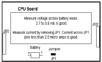
Voltage Check:
Measure the battery using a DVM set on the DC volts setting.
If the meter reads between 2.7 and 3.6 VDC the battery is still
good and does not need replacing. If the meter reads below
2.7 VDC, replace the battery with a recommended replacement.
(Saft, Lithium 3.6V PN LS 14250 or equivalent.)
Current Check:
Locate jumper JP1 and remove it. Set the meter to read
current (micro amps). Hook the meter up across the JP1
pins. The current should be less than 2.5 micro Amps.
Replacement:
Locate jumper JP1 and remove it. This will disconnect the
battery circuit from the rest of the board and prevent damaging
other components when soldering in the new battery.
On the component side of the board remove (scrape off) the
silicon beads protecting the solder joints.
It is best to cut the leads and remove the old battery first.
Then carefully unsolder the leads making sure to not lift the
pads on the board. Make sure the feed-throughs are free of
solder and the axial leads of the new battery can be installed.
Properly orient the new battery and solder it in place. It is
recommended to place a silicon bead over the battery connections
on the clad side of the board.
Replace jumper JP1 and reassemble the unit.
Replacement is complete.
Back to the top.


